- Support
-
 Questions

0
Answered
Philips RJ45 Port Wiring
Hi,
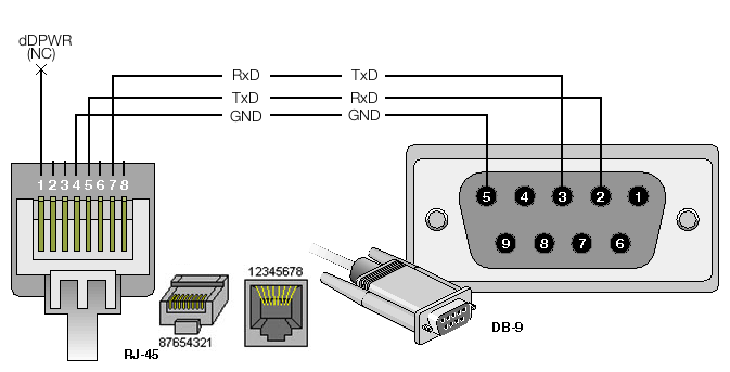
I've been working with a Philips IntelliVue MX800, and the associated RJ45 to RS232 adapter required.
I've been left a little confused after seeing the below diagram on your website. It appears to me that the white numbers on the left-most diagram of the RJ45 connector appear to be inconsistent with the two other diagram of the RJ45 connector.
This is based on the assumption that the left-most diagram is displaying and end-on view of the RJ45 connector.
Answer

Answer
Under review
Hey Thomas,
The left-most diagram is a cross section of a male connector plugged into a female connector. Use the pin connection numbering described by the drawing with the pin layout of the smaller drawings. The pinouts on the two smaller individual illustrations are the correct layout for each gender connector. The pin numbering is standardized so feel free to Google around for better pictures.
Thanks,
Jeff
Right, that makes sense. Just wanted to make sure, in case the source of my issues was cabling!

Customer support service by UserEcho

The left-most diagram is a cross section of a male connector plugged into a female connector. Use the pin connection numbering described by the drawing with the pin layout of the smaller drawings. The pinouts on the two smaller individual illustrations are the correct layout for each gender connector. The pin numbering is standardized so feel free to Google around for better pictures.
Thanks,
Jeff